Project creation
Creates a clean workspace with the dimensions and data needed for a new cutting project.
Design software
The design module creates the digital geometry that later becomes a cutting path for the CNC driver. It was built to make the full CNC workflow visible: project setup, drawing, point editing, storage, and machine preparation.
Workflow
The software lets the user create a project, draw points and paths, review the geometry, and store the data required by the control application. It works as a compact educational CAD/CAM layer for the prototype.
The main idea is traceability: each drawing action can be followed from the screen to the saved coordinates and then to the driver software that controls the router.
Core features
Creates a clean workspace with the dimensions and data needed for a new cutting project.
Opens saved work either from the project list or directly from a file, keeping the drawing workflow simple.
Allows points and paths to be placed directly on the working area.
Displays the coordinates and point data that define the cutting path.
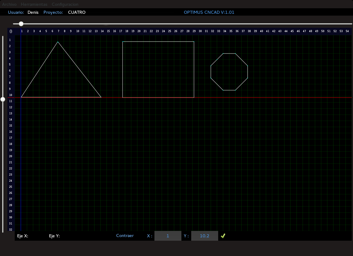
Shows the drawn geometry before it is sent to the CNC driver.
Keeps project information organized so the driver can interpret the cutting path.
Screens and diagrams
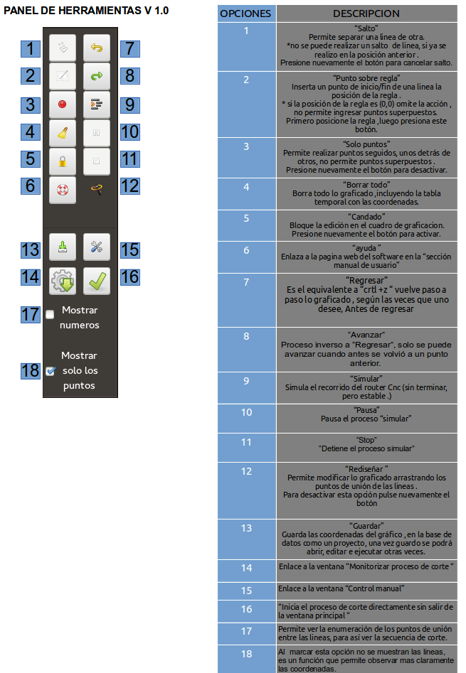
Controls used to build and edit the design.
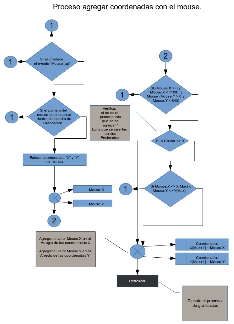
Diagram showing how points are captured from the workspace.
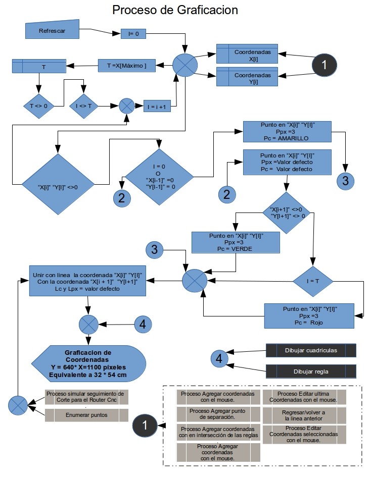
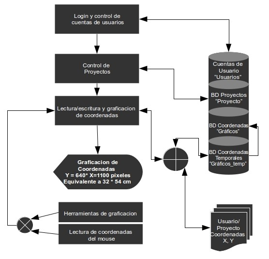
Relationship between drawing actions and generated data.
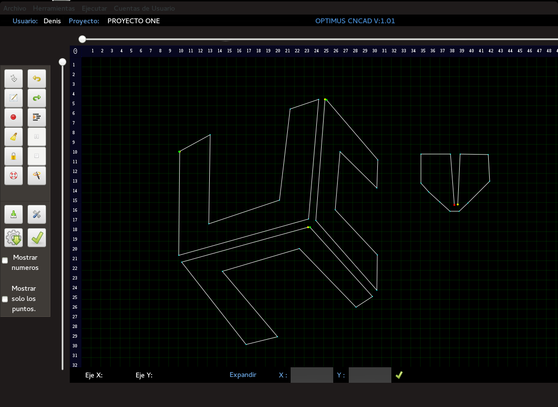
Design workspace with an active cutting project.
Saved design data shown inside the software interface.
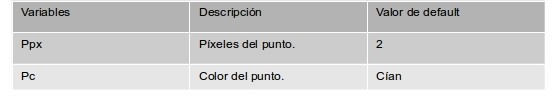
Coordinate values used to describe each point in the path.
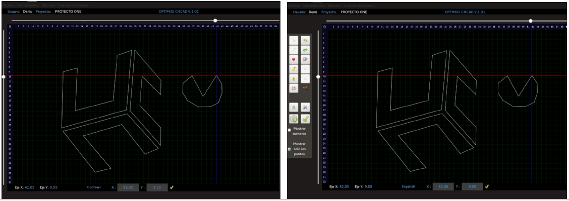
Expanded view for inspecting the drawn geometry.
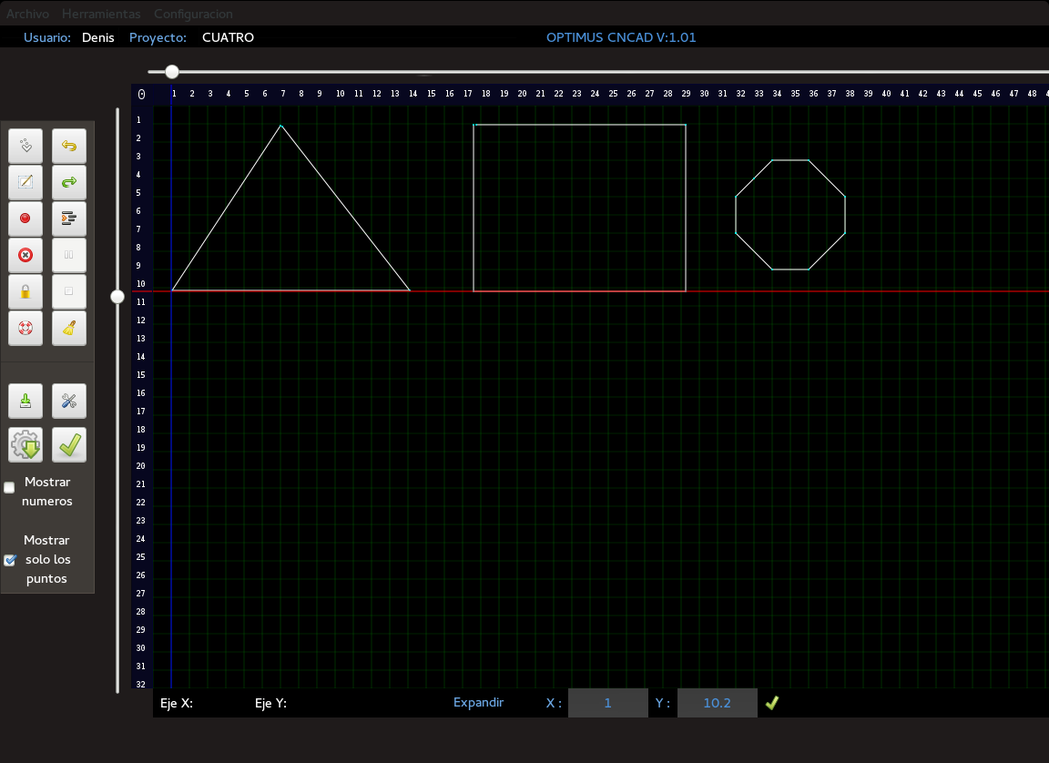
Workspace view with the tool panel visible.
Animated references
Creating a project before drawing the tool path.
Loading an existing project into the workspace.
Capturing points directly from user interaction.
Interface controls used during design.

How point variables support the saved cutting path.
Visual flow from drawing to path preview.