Connection interface
Adapts the computer output to the control board. It separates the software layer from the power stage and gives the project a clear place to organize each signal.
Electronics
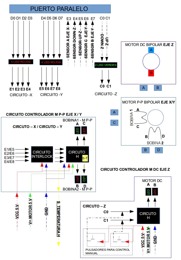
The electronics stage links the computer to the motors, sensors, and protection elements required by the CNC router. In this prototype, the control path starts in the CNC Driver software, leaves the computer through the parallel port, passes through logic and protection circuits, and reaches the motor driver stage that moves each axis.
Signal flow
The CNC Driver does not move the machine directly. It sends step and direction states through the computer output pins. The electronics convert those low-current logic signals into controlled power for the motors, while the sensor and protection circuits help prevent movement outside the expected limits.
This approach keeps the project easy to study: every axis can be understood as a chain of software instruction, logic signal, driver output, and mechanical displacement.
Circuit blocks
Adapts the computer output to the control board. It separates the software layer from the power stage and gives the project a clear place to organize each signal.
Provides a basic view of the operating state. Monitoring is useful while testing because it shows whether signals are reaching the expected part of the circuit.
Helps avoid unsafe states before they reach the driver stage. In a CNC machine this matters because a wrong signal can move an axis in the wrong direction or hold a motor energized.
Control current direction through the motor coils. This allows the circuit to drive bipolar stepper motors and reverse movement when the driver changes direction.
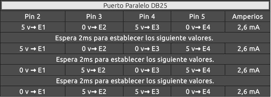
Uses the DB25 output pins as the communication path between the GNU/Linux software and the electronics. Each pin can represent a step, direction, enable, or control state.
Move the axes in small increments. This makes them practical for a prototype router because the software can count steps and translate coordinate changes into physical displacement.
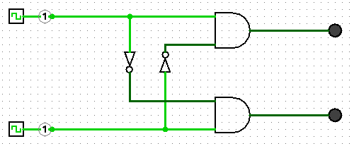
Use simple digital logic to combine or validate signals before they reach the drivers. This keeps control behavior predictable and easier to troubleshoot.
Provide feedback from the machine. Limit or position sensors help the driver understand when an axis reaches a defined point or needs to stop.
Protection and interlock
The interlock section acts as a safety layer between command signals and motor output. Its purpose is to prevent contradictory or unexpected states from reaching the motor drivers.
For a small educational CNC router, this is especially important during manual control and initialization. The operator may test one axis at a time, reverse directions, or move the tool close to the material, so the circuit should make those operations easier to observe and less likely to damage the mechanism.
Motor driving
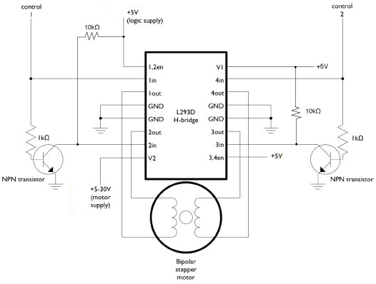
Bipolar stepper motors need their coil current to change direction in a controlled sequence. The H-bridge and L293-style driver references show how the project can energize the coils from logic-level commands.
The CNC Driver software decides when an axis should move. The electronics provide the electrical force needed to make that movement happen, one step at a time.
Reference images
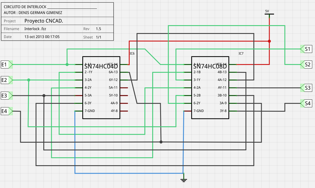
Protection and logic reference for safer operation.
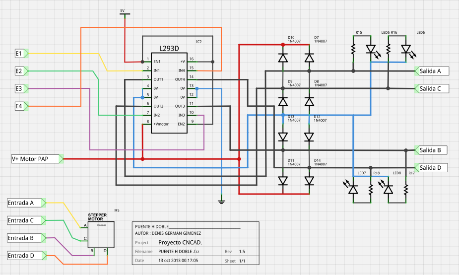
Motor driving circuit used by the prototype.
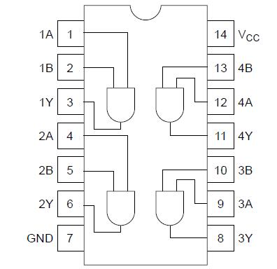
HD74HC08 pinout reference.
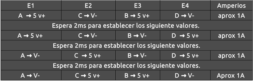
Control circuit reference for one machine axis.
Data bus relationship with the X axis motor control.
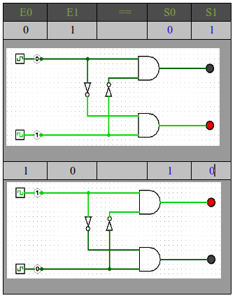
Detailed view of the protection circuit logic.
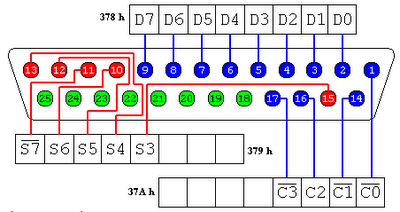
Parallel port pin reference for computer control.
Bipolar stepper motor control using an L293B style driver.
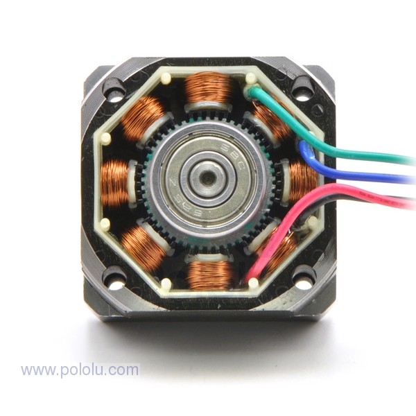
Motor reference used for axis movement.