Stable base
The base keeps the X axis aligned so the cutting path can be repeated with less variation.
Mechanical system
The mechanical prototype combines an X axis, a moving Y axis, and a two-position Z axis to guide the cutting tip over the workpiece. The structure is simple enough to study and build with common mechanical parts, while still showing the basic relationship between software coordinates and real motion.
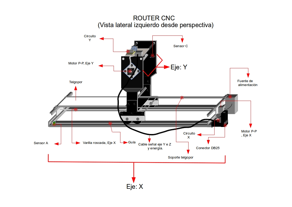
Axes
The X axis works as the base. The Y axis moves across it, and the Z axis raises or lowers the cutting tool. This structure is enough to position the cutter, contact the foam, move through the path, and lift away when needed.
The design uses threaded rods, stepper motors, structural plates, and a cutting tip assembled into a small router for expanded polyethylene. The mechanism favors visibility over compactness: each axis can be observed, adjusted, and related back to the driver software.
Mechanical role
The base keeps the X axis aligned so the cutting path can be repeated with less variation.
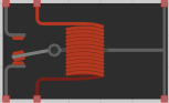
Threaded rods and motor rotation convert electrical steps into linear displacement.
The Z axis separates cutting movement from travel movement, reducing unwanted contact with the material.
Build references
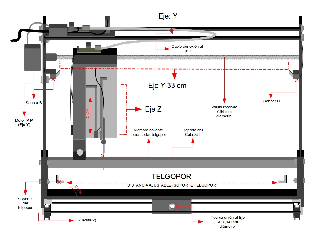
Base movement structure.
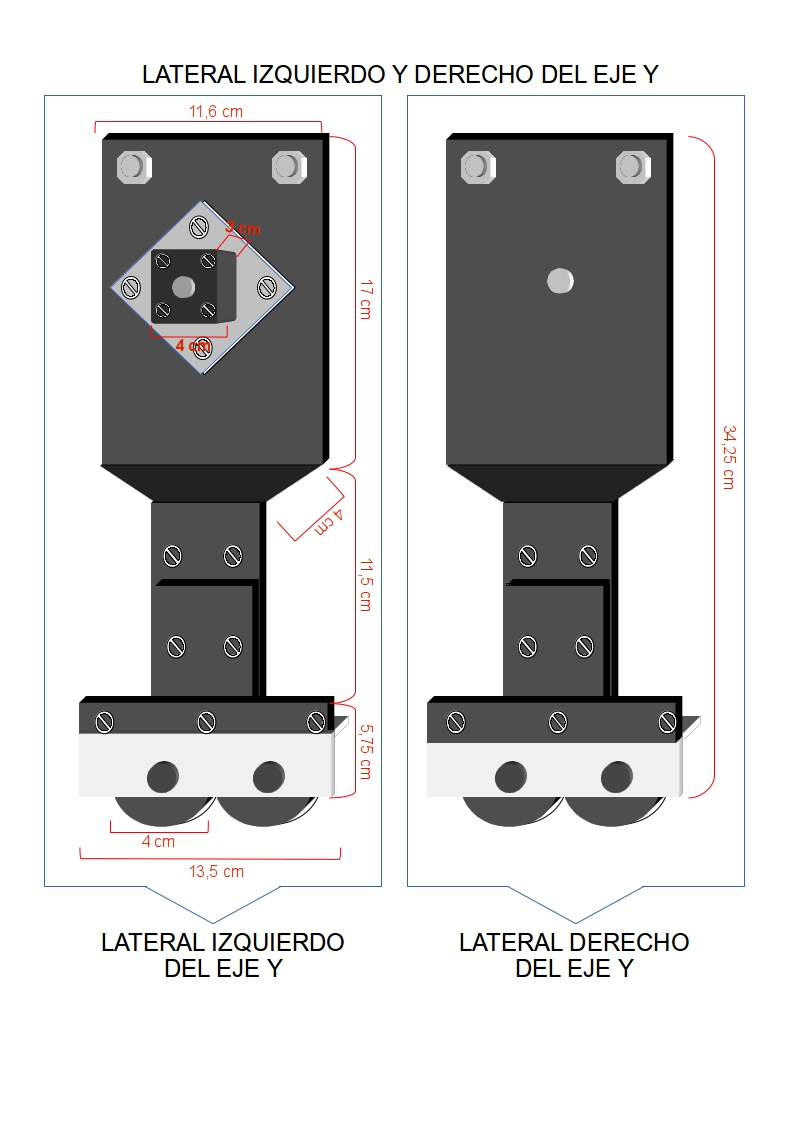
Side view of the Y axis assembly.
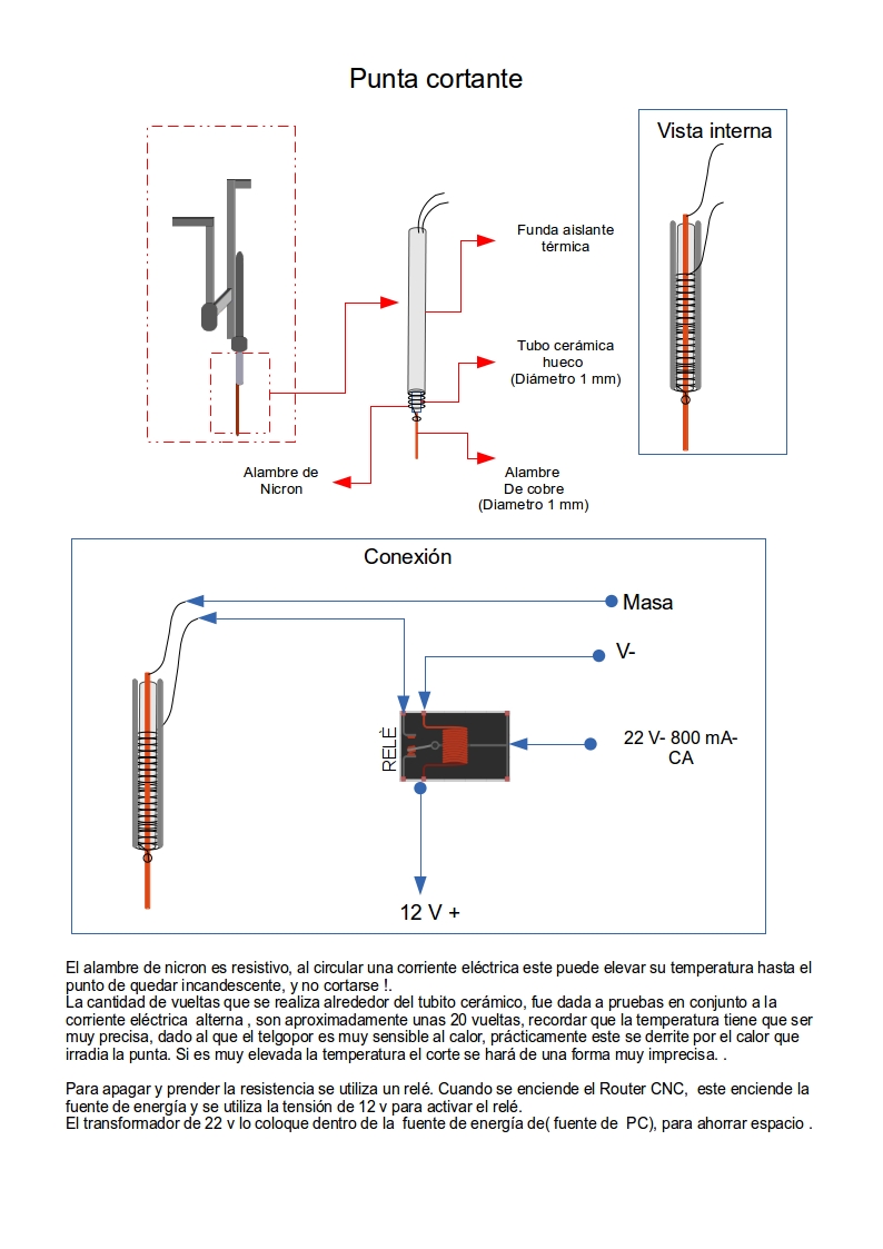
Tool contact area for foam cutting.
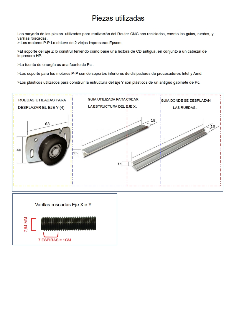
Main mechanical elements used in the build.
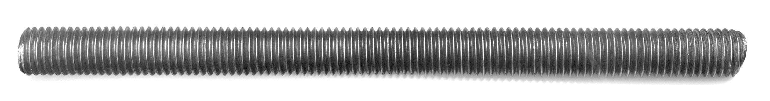
Linear motion component prepared for the axes.
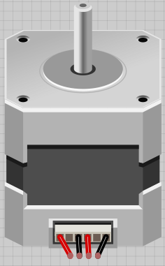
Motor reference for controlled mechanical movement.
Animated view of the router concept.
Auxiliary component reference from the project.
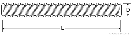
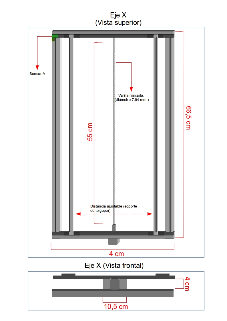
Dimensional reference for mechanical planning.